I’ve always been the type to double-check the door before leaving. Not out of fear exactly, I lived in a fairly secure neighborhood, but out of a need for certainty. There’s a quiet but persistent gap between “it’s probably fine” and actually knowing it is. The area was decent, the crime rate low, yet every time I stepped out, the ritual was the same: lock the door, walk a few steps, turn back, check again. Sometimes twice. Sometimes more.
That feeling only grew stronger when work started taking more of my time. Long days at the office turned into evenings, and eventually into trips where I’d be away for weeks at a time. Each departure came with the same restless question trailing behind me: is everything really okay back home?
It wasn’t lost on me how irrational it sounded. By most measures, things were safe. But peace of mind isn’t always logical. It’s personal. And for me, “reasonably safe” never quite settled the mind.
So I did what any technically inclined, slightly obsessive person would do — I built something to fix it.
I’m writing about it now because that chapter has quietly closed. When I moved, I dismantled the system and never felt the need to set it up again. Recently, while clearing out things I no longer use, I stumbled on a box stuffed with wires, sensors, and parts from that project. It was a mess, but also a time capsule, a reminder of a practical little system that once solved a very real problem for me, and a project I genuinely enjoyed building.
The Problem with Padlocks and Peace of Mind
The physical setup was straightforward but not exactly reassuring. My metal door had a padlock on the inside accessible through a hole in the door, large enough for a hand and the padlock to fit through and a lid to cover the hole. So someone could open the cover, reach through and either pick the lock or, more realistically, just cut it with bolt cutters. The hole was right there. The lock was exposed. A determined person with basic tools and thirty seconds of privacy? They'd be through.
When I was away at work, I had no idea if someone was even testing the lock. When I was on holiday, that nagging thought would pop up at the worst times: "Did I actually lock it, or did I just think I locked it? Has someone broken in?" I'd mentally retrace my steps, trying to remember if I heard that satisfying click. Sometimes I was sure I had. Sometimes I wasn't.
I needed two things: visibility and backup. I wanted to know what was happening at my door when I wasn't there, and I wanted a second layer of security that couldn't be defeated with a hardware store purchase and thirty seconds of aggressive enthusiasm.
Why Build Instead of Buy?
Why not just buy a commercial security system? Ring doorbells, smart locks, full alarm systems, there are plenty of options out there.
While some of these products do make their way into Kenya, they’re often expensive imports with limited local support. If something fails, you’re dealing with warranties, shipping, or vendors thousands of miles away. Even simple replacements can turn into a process.
But the bigger truth is that I didn’t spend that long researching what to buy, because part of me already knew I wanted to build something instead.
I’d been tinkering with Arduino since campus days: temperature sensors, blinking LEDs, small motor projects that worked beautifully for a week before ending up in a drawer. This felt different. This was a chance to build something practical. Something I’d rely on every day, not just experiment with and forget.
And the DIY route had real advantages. I had full control over how it worked, could repair it myself, avoided subscriptions, and could tailor it exactly to my space and habits. That combination — curiosity, usefulness, and control — made building feel like the more natural choice.
The Vision: Layers of Security and Information
The core concept was simple: defense in depth with real-time visibility.
The padlock would stay. It was the first line of defense and kept everything looking normal from the outside. Behind it, I planned to automate the internal lock using a linear actuator — essentially a motor that pushes and pulls a metal rod to drive the bolt. This wouldn’t make the door impenetrable, but it added a second barrier that wasn’t visible or accessible from outside. Even if someone dealt with the padlock, there was still another lock holding from the inside.
For visibility, I wanted sensors placed around key points: reed switches to detect whether doors were open or closed, a PIR motion sensor to catch movement outside, and possibly a camera. Everything would report back to me wherever I was — at work, on holiday, anywhere with an internet connection.
Designing it myself meant I could build exactly what I needed:
- Lock and unlock the door remotely(useful when I needed to grant access while away)
- Check door status at any time
- Get motion alerts with photo evidence (ESP32-CAM would capture who was at the door)
- SMS fallback for commands, in case internet access failed
- Auto-lock logic: door unlocks, opens, closes, system waits ~30 seconds, then locks again
I sketched the architecture one evening and it looked achievable. Two Arduino Nano controllers, a few sensors, an old phone, and some ESP modules for Wi-Fi. The parts I needed to buy would cost roughly Ksh 8,000–10,000, and I already had about half of them in my electronics drawer. The linear actuator was the most expensive piece at around Ksh 4,500. Everything else was fairly cheap: ESP-01 modules at about Ksh 300, reed switches at Ksh 50 each, and the motion sensor around Ksh 150.
Building It: The Components Come Together
Dividing the Labor
One of the first design decisions was using two Arduino Nanos instead of trying to make one handle everything. On paper, a single controller could have done the job. In practice, splitting responsibilities made the system simpler and more reliable.
The first Arduino acted as the main controller. It stayed on 24/7, monitoring sensors, handling communication through an attached ESP Wi-Fi module, and sending alerts. Its job was to quietly watch for changes and report them.
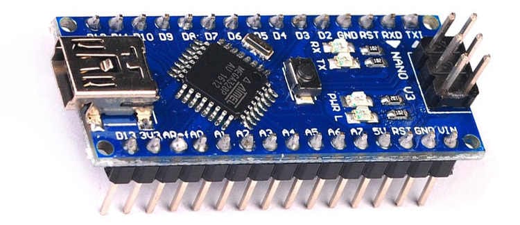
Arduino Nano
The second Arduino was dedicated to the lock mechanism. It only powered on when needed and existed for one task: driving the linear actuator that moved the internal bolt. I wired its power supply through a relay controlled by the main Arduino. When a lock or unlock command came in, the main controller would switch on the relay, power up the lock controller, let it do its job, then cut power again.
This separation helped in a few ways. The actuator drew more current and could introduce electrical noise, so isolating it reduced the chance of crashes. It also saved power, since the second controller wasn’t running continuously. The only tradeoff was a short boot-up delay whenever it powered on, which was acceptable.
The Brain: An Old Android Phone
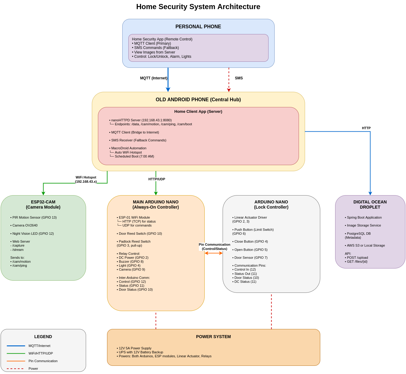
At the center of everything was an old Android phone that had been sitting unused. I turned it into a hub by setting it up as a permanent Wi-Fi hotspot and running two pieces of software on it:
- A lightweight HTTP server (nanoHTTPD) that the Arduinos could talk to locally
- An MQTT client that connected to the cloud, bridging local and remote communication
This setup was simple. The Arduino would post status updates to the phone's local server, "Door closed, padlock secure, alarm armed", and the phone would relay that information to MQTT (Message Queue Telemetry Transport, a lightweight messaging protocol perfect for this). My personal phone, wherever I was in the world, subscribed to those MQTT topics and showed me the current status.
Why an old phone instead of a Raspberry Pi? Because I had the phone. But it turned out to be a great choice: built in screen for debugging, battery backup if power flickered, LTE connection for redundancy if WiFi failed, and enough processing power to handle everything without breaking a sweat.
The Sensors: Eyes and Ears
I installed reed switches on both the padlock hole cover and the door. These are magnetically actuated contacts. When a magnet comes close to the switch, the internal metal reeds pull together and close the circuit. When the magnet moves away, the reeds separate and the circuit opens.
By mounting the magnet on the moving part (door/padlock cover) and the switch on the frame, I could electrically detect state: circuit closed meant the door was shut, circuit open meant it had been opened. Simple and reliable.
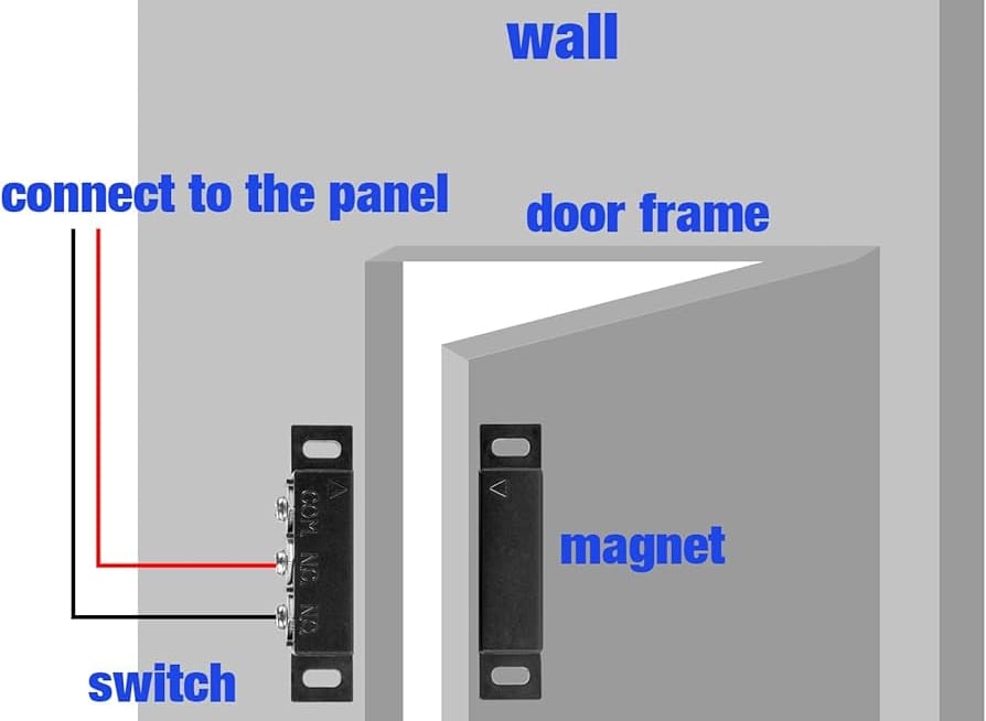
Reed switch installation on a door
A PIR (Passive Infrared) motion sensor covered the approach to the door. When it detected movement, it triggered the ESP32-CAM module.
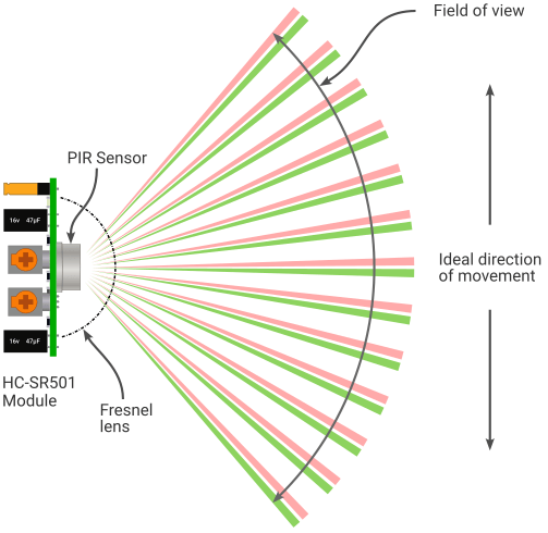
The ESP32-CAM is a compact board with a 2MP camera and built-in Wi-Fi. On motion events, it captured a photo and uploaded it to my cloud server, a small Spring Boot application running on DigitalOcean. The Android hub then published the image URL via MQTT, which triggered a notification on my phone: "Motion detected" along with a thumbnail.
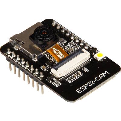
End to end, the capture, upload, and notify sequence took about 3 to 5 seconds. Fast enough to catch anyone who walked up to the door, even if they didn’t stay long.
The Lock: Muscle and Control
The linear actuator was the physical heart of the system. It’s essentially a DC motor driving a lead screw. Apply power one way and a metal rod extends; reverse the polarity and it retracts. I mounted it inside and linked it to the door’s internal locking mechanism.
Controlling it required an H-bridge motor driver (L298N), which let the Arduino reverse the motor’s polarity. One direction meant extend (lock), the other meant retract (unlock). The lock-controller Arduino simply drove the inputs and the actuator handled the rest.
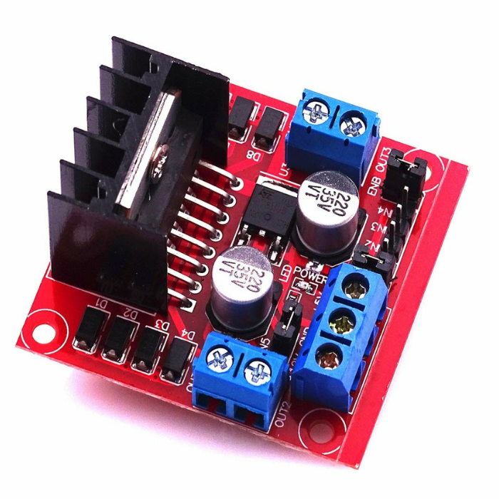
H-Bridge motor driver
The clever bit was the limit switch on the retract side. When unlocking, the actuator would pull back until it hit a physical switch, which told the controller, “fully open, stop now.” That prevented over-travel and protected the motor.
For locking, I took a simpler approach. I measured how long it took to fully extend and just ran the motor for about 8 seconds, then cut power. Not as elegant as having a second limit switch, but it was predictable and worked reliably in practice.
The auto-lock feature ended up being more useful than I expected. The flow was simple: the door unlocks (either remotely or manually), someone enters, and once the door closes, the main controller detects the closed state from the reed switch. It waits 30 seconds, then commands the lock controller to extend the actuator and secure the door again.
In theory, I could unlock the door for a delivery person while away, they’d drop off the package, close the door, and the system would re-lock automatically without me needing to remember to send another command.
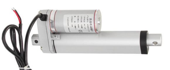
A Linear Actuator
The Communication Web
The main Arduino connected to an ESP-01 WiFi module over UART. It sent AT commands over serial to configure the connection, join the phone’s hotspot, send HTTP POST requests, and open a UDP socket for incoming commands.
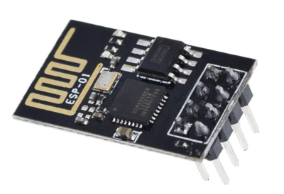
ESP8266-01 Wifi Module
For command delivery, I used UDP. The commands were short and idempotent — “lock” or “unlock.” If a packet was lost, I could simply retry. The low overhead and stateless nature of UDP made it a good fit for fast, local control.
The ESP32-CAM had its own WiFi connection. When motion was detected, it notified the Android hub, which instructed it to capture a photo. The image was then sent back to the phone and uploaded to my Spring Boot server on DigitalOcean. Once uploaded, the app published the image URL via MQTT so my personal phone could display the alert.
The Android phone orchestrated everything through a custom app. The Arduino posted status updates every 10 seconds. The app logged them to an embedded ObjectBox database and published the latest state to MQTT. Commands received from my personal phone were forwarded locally as UDP packets to the Arduino.
And the SMS fallback? That was my contingency layer. If I lost mobile data entirely, I could send a simple command like “d0” to the old phone’s number. The app would parse the SMS, verify it was from my number, and forward the command to the Arduino over the local network. I never had to use it in production, but knowing it was there made the system feel complete.
The Power of Paranoia
I ran everything off a 12 V 5 A supply with a 12 V battery-backed backup system. Under normal conditions, the system ran directly from mains power. If power failed, it automatically switched to the 12 V battery without interruption.
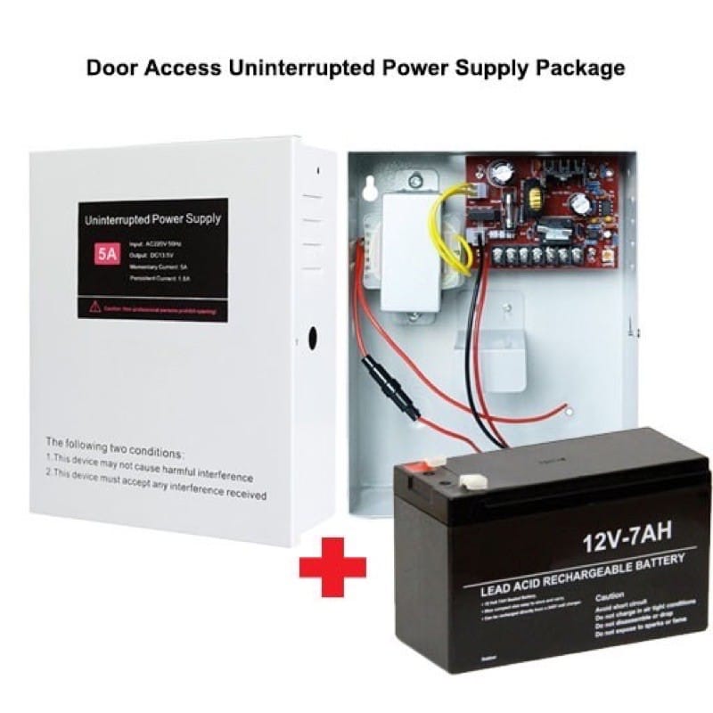
The Arduinos, relays, and other modules were powered through voltage regulators that stepped the 12 V down to a stable 5 V. The linear actuator drew directly from the 12 V rail. If mains power went out, the battery could keep the system running for several hours, long enough for me to notice and respond.
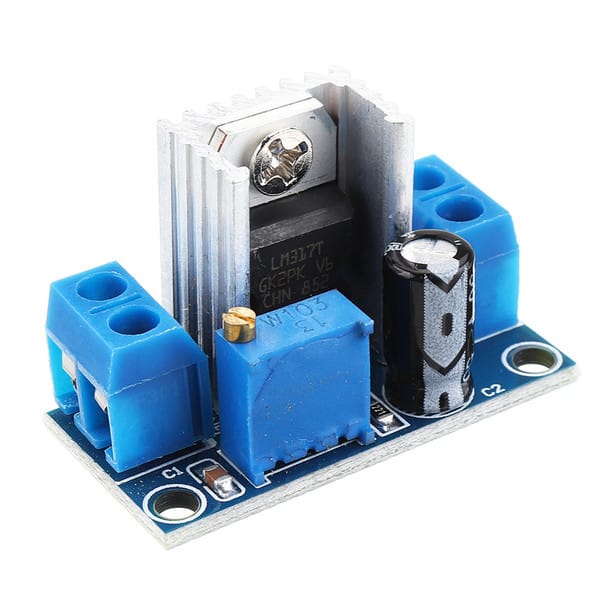
voltage regulator
The old phone had its own internal battery, which added another independent layer of redundancy. Even if the 12 V system failed entirely, the communication hub could stay alive for a while.
I also configured MacroDroid (an Android automation app) to automatically re-enable the Wi-Fi hotspot if the phone ever restarted.
The Rough Edges: What Didn't Go Smoothly
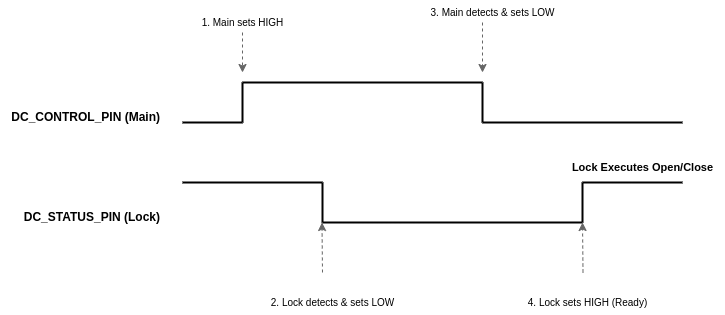
The inter Arduino communication protocol, using digital pins to signal between them, felt inelegant. I wanted them to talk over serial, but I'd already used those pins for the WiFi modules. So instead, I built a simple handshake: Main Arduino raises a pin high, Lock Arduino sees it and acknowledges by lowering another pin, command executes, pins reset. It worked, but every time I looked at that code, I thought "there's got to be a better way." There probably was. But this one worked, and working beat perfect.
The auto reset feature, where the main Arduino rebooted itself every 30 minutes for stability, was a band aid over a memory leak I never quite tracked down. The Arduino would slowly consume RAM over hours until it became sluggish. Rather than dig through my code for the leak, I just had it restart periodically. Inelegant? Yes. Effective? Also yes.
Living With It: Eighteen Months of Peace of Mind
Once everything stabilized, which took about two weeks of tinkering and tweaking, the system just worked.
False alarms were rare but educational. The most common culprit was wind. Strong gusts would occasionally shift the padlock hole cover just enough to separate the magnet from the reed switch, triggering an alert: “Cover opened.” I’d check the latest camera snapshot and see nothing there. Just wind. Eventually, I added a small magnetic latch to hold the cover firmly in place, which mostly solved the problem.
The motion sensor had its own quirks. My neighbor walking past in the corridor would sometimes trigger it, depending on the angle. Rather than getting constant alerts from normal foot traffic, I adjusted the sensor’s position and sensitivity until it reliably caught people actually approaching my door while ignoring passersby.
The peace of mind was tangible. I stopped triple checking if I'd locked up. I stopped worrying on holiday. When that little thought started to creep in, "Did I lock the door?", I'd check my phone. Status: Locked. Timestamp: a few seconds ago. Okay, I'm good.
The End of an Era
After about a year and a half, my living situation changed. I moved to a more secure place with proper building security and less need for the elaborate system I'd built.
Decommissioning it felt strange. I'd spent so many hours building it, debugging it, living with it. It had become part of my daily routine: check the door status, review any motion alerts, feel that quiet reassurance.
I salvaged the components. The Arduinos went back into the parts bin for future projects. The old phone went back to being, well, an old phone. The linear actuator is still in storage, waiting for the next project that needs something pushed or pulled with authority.
Part of me felt nostalgic taking it apart. This system had given me genuine peace of mind for eighteen months. It had worked when I needed it. It had proven I could build something useful, not just something clever.
But mostly, I felt satisfied. I'd had a problem. I'd built a solution. It worked. Mission accomplished.
Final Thoughts: The Joy of Building What You Need
There's something deeply satisfying about solving your own problems. Not with someone else's solution that almost fits, but with something you designed specifically for your needs.
Commercial security systems are great for most people. They’re polished, supported, reliable. But they’re one-size-fits-all, and sometimes your situation doesn’t fit the mold. Or sometimes, and this is equally valid, you just want to build something yourself.
If you're considering a similar project, here's what I'd say:
Start with a clear problem. "I want to learn Arduino" is fine, but "I want to know if my door is locked when I'm away" is better. The concrete goal keeps you focused when debugging gets frustrating.
Embrace iteration. My first version didn't have the auto lock feature. The motion detection went through three different configurations. The MQTT topics changed a number of times. That's fine. Build it, use it, improve it.
Expect to spend time debugging. My total time investment was probably 60 to 80 hours spread over a month, mostly evenings and weekends. That’s just the build phase. If you’re not willing to debug weird WiFi issues at 11 PM, commercial solutions might suit you better.
Document as you go. I didn't, and later when I wanted to adjust something, I had to reverse engineer my own work. Learn from my mistake.
And finally, it's okay to over engineer for peace of mind. Is SMS fallback overkill? Probably. Did knowing it was there help me relax on holiday? Absolutely. You're building this for you. Make it as robust as you need it to be.
Looking back, the project wasn’t just about securing a door. It was about building confidence in my ability to solve problems that actually matter. The system is gone now, packed away in a box, but that mindset stuck around. And that might be the most valuable thing I built.
The technical documentation, code, and setup instructions, is available on GitHub. For those interested in the nitty gritty details of the architecture, pin assignments, and communication protocols, I've documented everything there.